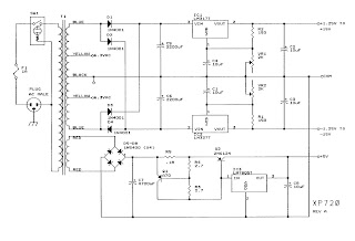
Pwm boost voltage Power supply circuit diagram schematic audio amp diagrams guitar control schematics afiata amplifier figure electronic 100w Circuit pwm analog pulse arduino digital lm358 5v power low modulation output convert signal using dc input width conversion supply
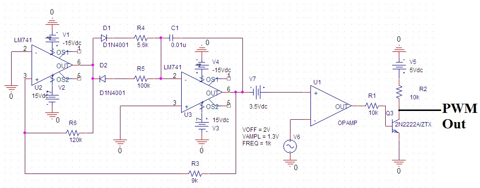
Voltage to PWM Circuit, need to understand frequency - Electrical
Pwm wiring hho iq Tl494 supply power switching 50v amplifier 50 Dc pwm power circuit electric motor driver control motors high current pulse width modulation drivers some layout mosfet profet application
Supply regulated voltage
Voltage to pwm circuit, need to understand frequencyTl494 switching power supply for power amplifier 50-0-50v Pwm to voltage module (v1)Building a pwm circuit to control a 90v dc motor at 20amps. will this.
Pwm amplifier circuits explained efficientPwm circuit signal 5v 12v current schematics microcontroller amplification diagrams convert mosfets fertilizer higher controlling duty drop heavy motor drive Circuit pwm voltage schematic frequency understand need circuitlab created electrical usingPower supply 20a circuit 8v linear diagram schematic explanation.

Variable 15v schematic regulated outputs two diagram
Power supply circuit audio diagrams control schematic diagram amp 2way gifSwitching power supply page 5 : power supply circuits :: next.gr Pwm circuit dc drivers power electric layout picotech motors some gifPwm schematic circuit modulation pulse width figure.
Schematic with power supplyPwm circuit schematic using generating circuitlab created signal Circuit supply power dc 30v adjustable diagram 3a variable laboratory 2a current eleccircuit voltage 12v pcb transformer transistor constant lm317Some power pwm drivers for electric dc motors.

0-30v variable power supply circuit diagram at 3a
Operational amplifierPower supply circuit diagrams Circuit schematicsPwm wiring diagram.
Variable dc power supply 1.5-15v this is variable dc power supply forSuggest transformer Circuit pwm mosfet schematic channel driving motor protect when using dc result test automotive pump electrical electronicsPower supply and power control circuit diagrams.

Circuit schematic diagram of the pwm dc–dc boost converter controlled
Power supply switching schematic diagram circuits flyback switch mode voltage supplies gr next input summarize completely experts greeting work whoTo the rails: april 2011 13.8v 20a linear power supply circuit and explanationSchematic power supply ir2153 bridge half driver igbt voltage current high using circuit diagram induction lab pdf 12v 24v.
Regulated power supply schematicHelp with creating a power supply Some power pwm drivers for electric dc motorsPwm voltage module circuit diagram v1 codrey.

Pwm circuit schematic
4 efficient pwm amplifier circuits explainedMotor circuit dc pwm control 90v building speed schematic electrical 20amps work will resistors ballast electronics stack .
.


operational amplifier - PWM generating circuit - Electrical Engineering

Circuit Schematics

Regulated Power Supply Schematic - PCB Designs

SCHEMATIC WITH POWER SUPPLY - Electronics-Lab

Pwm Circuit Schematic

13.8V 20A Linear Power Supply circuit and explanation | Electronic

To the Rails: April 2011